TimeHat ❤ Nokia FYGM
For the past few monts GNSS-disciplined time servers have been taking up a large percentage of my hobby time. Building and distribuiting the TimeHat went very well, and it gave me a bit of extra capital to dig into a few things that I might not have been able to otherwise, like picking up some "real" GNSS timing modules! The unit I was most interested in was the Nokia FYGM, a GNSS timing receiver made to work with Nokia cell site equipment. The FYGM has a u-blox LEA-M8T, one of the better timing-focused u-blox modules available. Lots of people buy these (and other) timing modules from decomissioned cell sites through Chinese scrappers and recyclers just to harvest the receiver, but I wanted to keep them as "together" as possible.
Unlike typical hobbyist GNSS modules, the FYGM has a some extra hardware on it, namely an 8051 MCU. I have more information on this on the wiki, here, so I'll keep this short. To start, why not simply emancipate the M8T from this board? I have a few reasons:
- I don't want to design a new carrier for the M8T
- The original board has high quality power supplies for the M8T and active antenna
- It also provides excellent antenna protection circuitry
- The included aluminium case is really nice
- The status LEDs (driven by the MCU) are useful
- Once the board boots, it's not hard to get the MCU out of our way
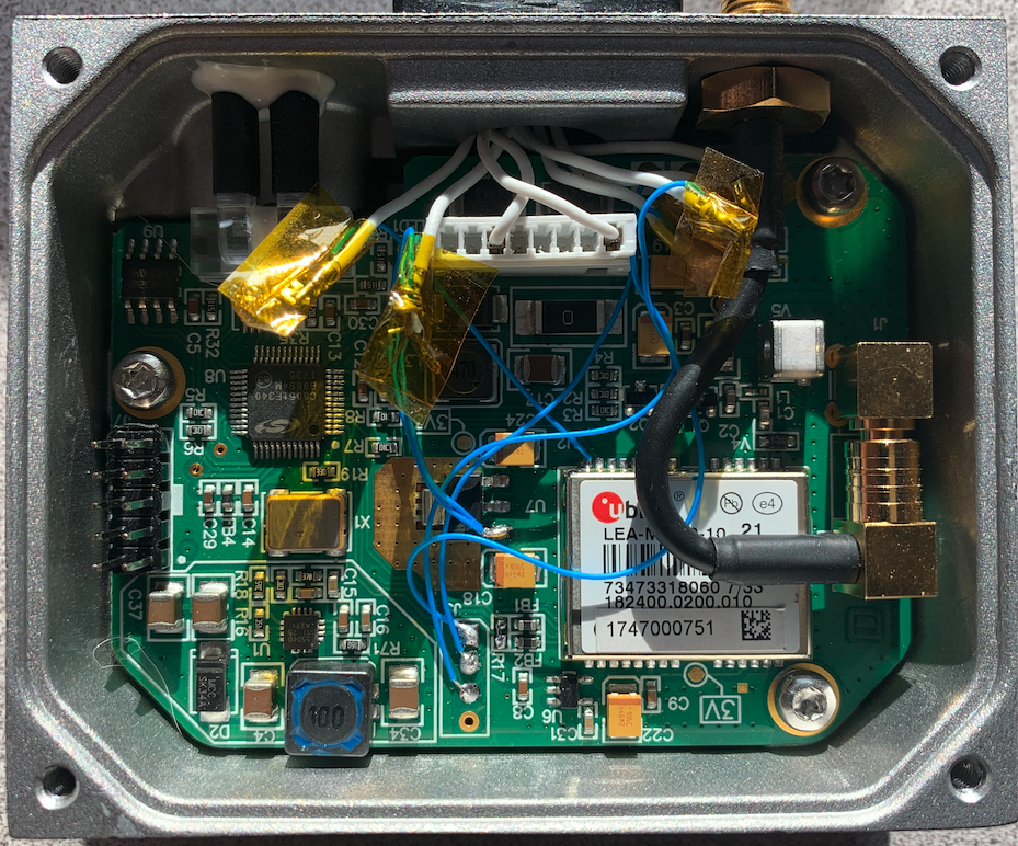
That MCU, the 8051, started as being the biggest thorn in my side. Before I had one of these units in my hands all I had to go off of was ebay listing pictures and a couple of posts on the TimeNuts mailing list, but that was enough to get started. In addition to antenna input, the FYGM has one other connector - a 12 pin DIN amphenol-looking thing. Thankfully all of the FYGMs I have found for sale inclide a completed cable to mate with this (using an HDMI connector on the host device end, with CAT7 as the cable itself), otherwise this connector could be a real pain to deal with, becuase it's not an amphenol, or anything that seems to be generally available. Only 8 of the pins on this connector are used, Ground, DC in (taking anywhere from 12 to 35v), and then three RS422 differential pairs for Tx, Rx, and PPS. Two RS422 transceivers on the bottom of the module provide this signaling. My initial intention was to try and use these as-is, so I got some hardware to work with RS422 - more on that later.
Once I got an FYGM in my hands, I started tracing all of the connectors and headers. I was disappointed to learn that the RS422 transeivers' input does not come directly from the M8T, but rather it from the 8051. This meant that it probably wouldn't be spitting out UART signals directly from M8T, something that turned out to be true. On the bright side, the four pin connector adjacent to the M8T is, in fact, UART directly from the M8T, meaning that bypassing the 8051 seemed like a possibility, and it technically still is. The ten pin connector next ot the 8051 is a programming and debugging header for that device, so perhaps one day I can read its configuration out or even reprogram it to make it more useful to me. The more immediate use that header has is the exposed reset pin - dropping a jumper between it and ground causes the 8051 to not boot at all, so through the UART pins next to the M8T I can interface with it directly, and completely ignore the MCU. I didn't end up doing this though.
Why?
Well, to put it plainly, the engineers who developed this thing had some clue as to what they were doing - remember, this device is intended to be a highly precise GNSS time source for a clock in a cell site. If we can benefit from the work they put into developing this thing, why not? When the FYGM boots, the 8051 sends a number of strings to the M8T to put it into a configuration that makes it optimal for use in its intended purpose - which just happens to be the purpose I have for it! As far as I have been able to tell, once these strings are sent, the 8051 gets out of the way entirely, it simply takes UART from the M8T, process it, and spits it out over R422. Initially this was a disappointment, but... I don't need to use the RS422 - I can run the signals straight from that UART header to the host - and that's exactly what I ended up doing.
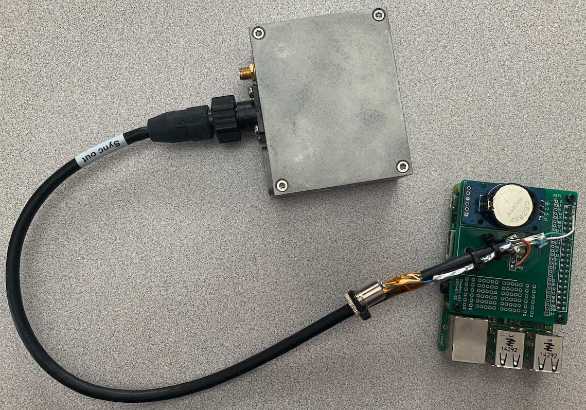
Early on I had started to design a Pi Hat with an HDMI port, a DC in jack for 12-35v, a 5v power supply for the Pi, and RS422 transeivers for the UART and PPS signals. As much as I like the aesthetic of this, it's just not reasonably feasible. Seeing as the UART from the M8T isn't connected directly to the RS422 transeiver on the FYGM, I would have to connect them directly with some bodge wires, but this means that the 8051 has to be taken out of the loop, and for the reasons described above, I don't want to do that anymore. What I ended up doing is pulling the pins out of the eight pin JST connector, everything but ground and DC in, and I am connecting to them directly to the UART signals out of the M8T. This also lets me do some sneaky stuff. It's kind of ugly, but it works well and allows me to continue to use the DIN connector which is solastic'd in place.
Again, this is ugly - but it works. If you look closely you can see the sneakyness... As you can probably tell from the picture at the top of this post, what I have done is cut the included cable down to about a foot and run it straight onto one of the TimeHat boards, feeding in Tx, Rx, and PPS just as the MAX-M8Q modules do. Power comes in through that barrel jack zip tied to the cable. If you look closetly, though, you'll see something going to the 5v pins of the TimeHat, what's up with that? Well, I spent a while think about how best to handle powering this whole mess, and I really liked the idea of integrating the Pi and FYGM as closely as possible. The UART header on the FYGM has a pin for 3v3 input, so I could power the M8T directly. The 8051 and active antenna circuits have their power power regulators though, these are fed from 6.3v coming from the main power supply on the board.
The Pi has no easy way to source 6.3v, but you know what? Turns out it will run just fine on 6.3v! I haven't spent much time at all studying the power front end on the Pi, so I just threw 6.3v on the 5v rail and sure enough, it works just fine! This may very well impact something in a negative light, but I'm just going to let it roll for now - I'll update if it causes any problems, but I don't suspect that it will. Basically, what I'm doing is feeing 16v into the FYGM's main power supply, then pulling the 6.3v back out and into the 5v rail on the Pi along with the other signals mentioned earlier. How much power is safe to sync from this 6.3v rail? Probably not a lot - but - keep in mind that I have the Pis that I use in this role configured for very low power consumption - no WiFi, no BT, no GPU, no USB devices, and the CPU is clocked down about as low as it can go. Using a kill-a-watt, I measured the whole setup to pull a whopping 1.9 watts from the wall, including all the power supply overhead.
What does this mean as far as time server performance is concerned? Well, I don't know yet. I haven't done much of that measuring yet. I just recently got my GNSS antenna splitter, so I can finally start to compare receivers using the same signal source, which is a step in the right direction. What really needs to happen next, before I can start seriously start making this measurements, is getting a GNSS antenna mounted up above the roof line. I have my mast built and brackets in place, all that's left is to actually attach it to the house - I'm still working on figuring that out, more to come shortly, I hope.
That said, even in my "less than optimal" configuration, things are looking good. The Pi here is a Pi2, and that is on purpose. Can pairing a less-than-optimal Pi with a really good GNSS receiver help? Who knows! Here's what the chronyc sources output looks like at the moment:
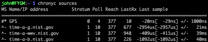
And here's what cgps looks like:
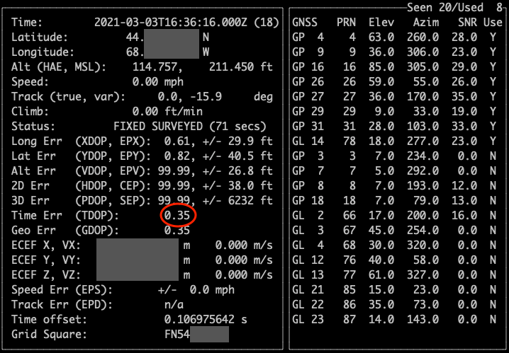
The 0.35 TDOP is what really stands out here. This receiver's antenna is in the basement, sitting on the ledge of a casement window. Using a high-mounted helical antenna sticking out of a 2nd story window I have seen TDOP below 0.2, so I expect this to improve well beyond the capabilities of the Pi once I get it mounted on the side of the house.