Building an End Fed Half Wave Transformer

Written by John Miller

The end fed half wave is a type of antenna system intended for use on the amateur radio HF bands, typically 80 meters through 10 meters. Its design is simple - a wire, a transformer, and a feed line. There are a number of different types of end fed wire antennas and they can be deployed in many different configurations. The end fed half wave antenna has a radiator that is approximately one half wavelength of the lowest frequency it is intended to be used on - give or take a bit for adjustment within the bands. In addition to a wire that is half wavelength, this antenna also has a transformer that brings the high impedance of a wire in free space down to the 50Ω that our radios crave. EFHWs are often referred to as "no-tune" antennas, because they tend to have an SWR that is usable without tuning across the primary band and its harmonics. The transformers that do this matching are often called "baluns" - but I'm not sure if that's correct. A balun is traditionally used to match a balanced line to an unbalanced line, and I don't know if the radiating wire of an end fed antenna is considered an unbalanced line.

There are already many guides and videos detailing how to make a transformer for an end fed half wave antenna, they aren't hard to find. I have thought about writing my own for a while, but I wanted wait until I had a build that I was very satisfied with before I put anything out there. Over the past two years I have built and extensively used a number of EFHW antennas, and I have been very pleased with their performance. Like many other topics in amateur radio, their mere existence is upsetting for some folks; but when you consider their performance, low cost, and very flexible deployment options you may understand why they are so popular. My first EFHW was a transformer and wire purchased from ebay - I purchased one because I thought building one might be too much trouble, I was very wrong about this! Furthermore, for what it's worth, there are many details of this build that are unique to me, either due to the parts I had on hand or because I just wanted to do something that way. This is a very flexible project - build yours how you want.

In my initial designs I used a 4" x 4" x 2" marine grade utility box an a large FT240-43 toroid. This is a big and somewhat clunky solution, and while it worked for me at the time, it has since been found that there are other toroids that are both smaller and more efficient at performing the same task. I credit Colin, MM0OPX, and his video "Best Ferrite Core For a 100w End Fed Half Wave Antenna" for my own discovery of this "new" toroid - though others have certainly been using this toroid for EFHWs before him, and he credits them in his materials. This "new" toroid is the Fair-Rite 2643251002, and it has been found to be more efficient than the FT240-43 across the entire HF band, while also being able to handle 100w of high duty cycle modes (such as FT8 or PSK31) for extended periods of time before saturating. I have replicated the results Colin discusses in his video by building two identical transformers, connecting them back to back, and calculating the dB loss through them both with a VNA.

Something I do want to mention briefly is that in addition to different toroid geometries, there are differences in their compositions as well, often referred to as their "mix". Both of these cores are mix 43. There are a number of different mixes that folks have found to be suitable for EFHW transformers, and 43 is one of them. I am not claiming that it is the best, only that it has worked well for me. If I had a much greater budget for this sort of testing I would like to get a few of each and really thoroughly compare them myself.

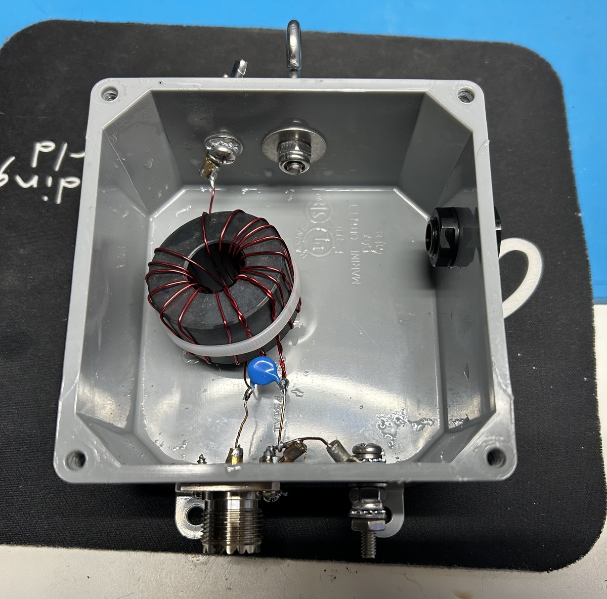
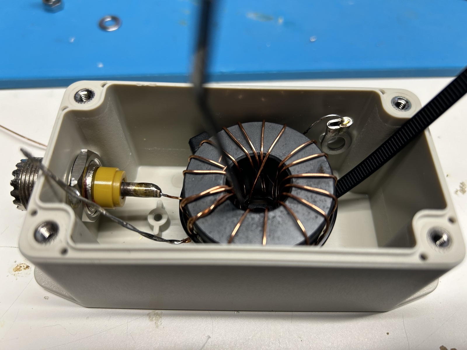
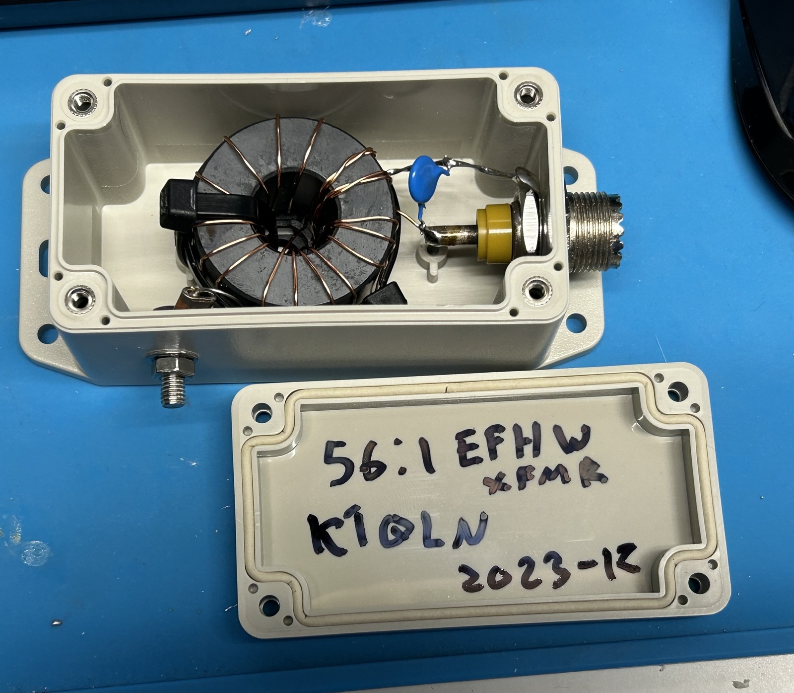
Since the 2643251002 is a good bit smaller than the FT240-43, 1.5" vs 2.4" across, it can be contained in smaller enclosures. The 2643251002 is a good bit thicker, at 0.9" compared to the FT240-43's 0.5", but I have yet to see an enclosure for the FT240-43 take advantage of this difference. The reduced size of the new toroid opened up a new window of opportunities for enclosures as you can see by this example of a 2643251002 in one of those 4x4x2 boxes - there is a lot of room in here.

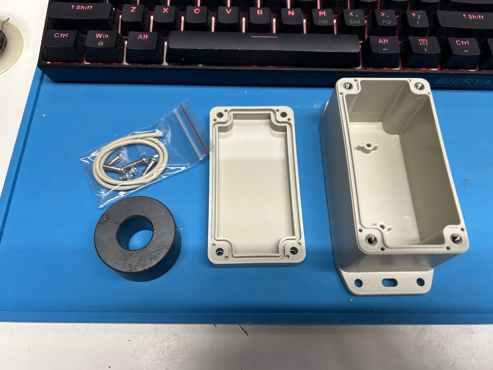
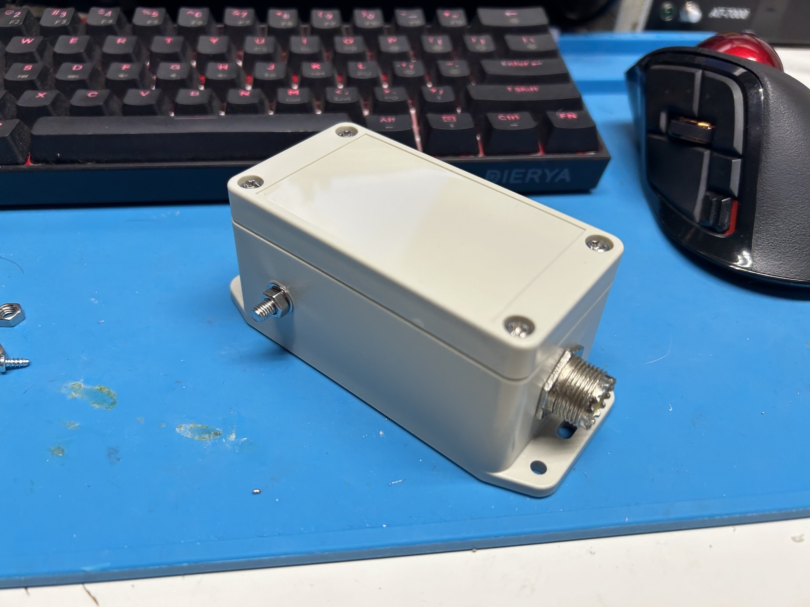
For what it's worth, there's not really anything wrong with this arrangement, but it can be neater. The enclosure I ordered for this variant is the Hammond RP1045BF, which is available at DigiKey for $10.80 vs $11.91 for the previous box I got from Home Depot. As you can see, it matches the 2643251002 very nicely.

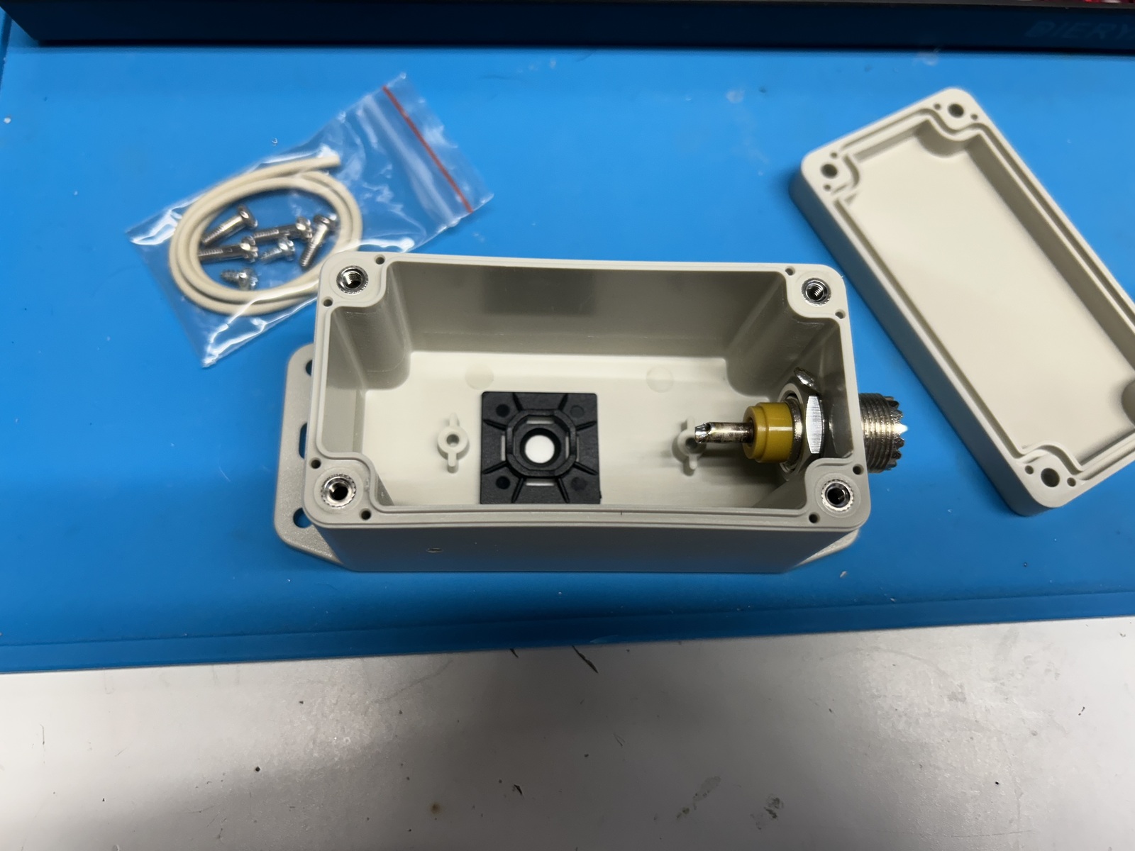
Assembly of these transformers is a mostly mechanical affair. After confirming that the toroid would indeed fit, I began laying out the enclosure. This particular model has tabs at the bottom and top molded into it that can be used to anchor the box to something else. In my case I chose to use them to suspend the box from the top holes via a hoist rope, as well as add a tension loop for the antenna wire itself - that will become clearer later on. Whatever enclosure you use, thinking about how it's going to be physically oriented is important, and you are going to want to make good decisions before you start drilling holes.

Since mine is going to be hung from the "top" tab, I decided to drill a hole for the coax connector in the bottom so that the feed line can drop straight down. In this case I had an SO-239 connector I had in my parts bin, but I plan to swap this for an N connector as that is what I prefer to use for outdoors permanent installations since N is inherently waterproof. SO-239 is fine if you take the right measures to protect it, and BNC is also a very popular choice, especially for portable use, since it's so easy to pop on and off. At this point I also installed a zip tie mounting point that I will use to anchor the transformer to. Some folks use glue or silicone, and I have done this in the past - but it can be messy or fail over time. Hammond also makes plates that can be screwed into the bottom of these boxes, but DigiKey doesn't stock them for whatever reason. I could make my own plate, or fab a PCB to be fitted there, as Colin did. I have had good luck with these zip tie plates in the past, and they can be removed easily if needed.

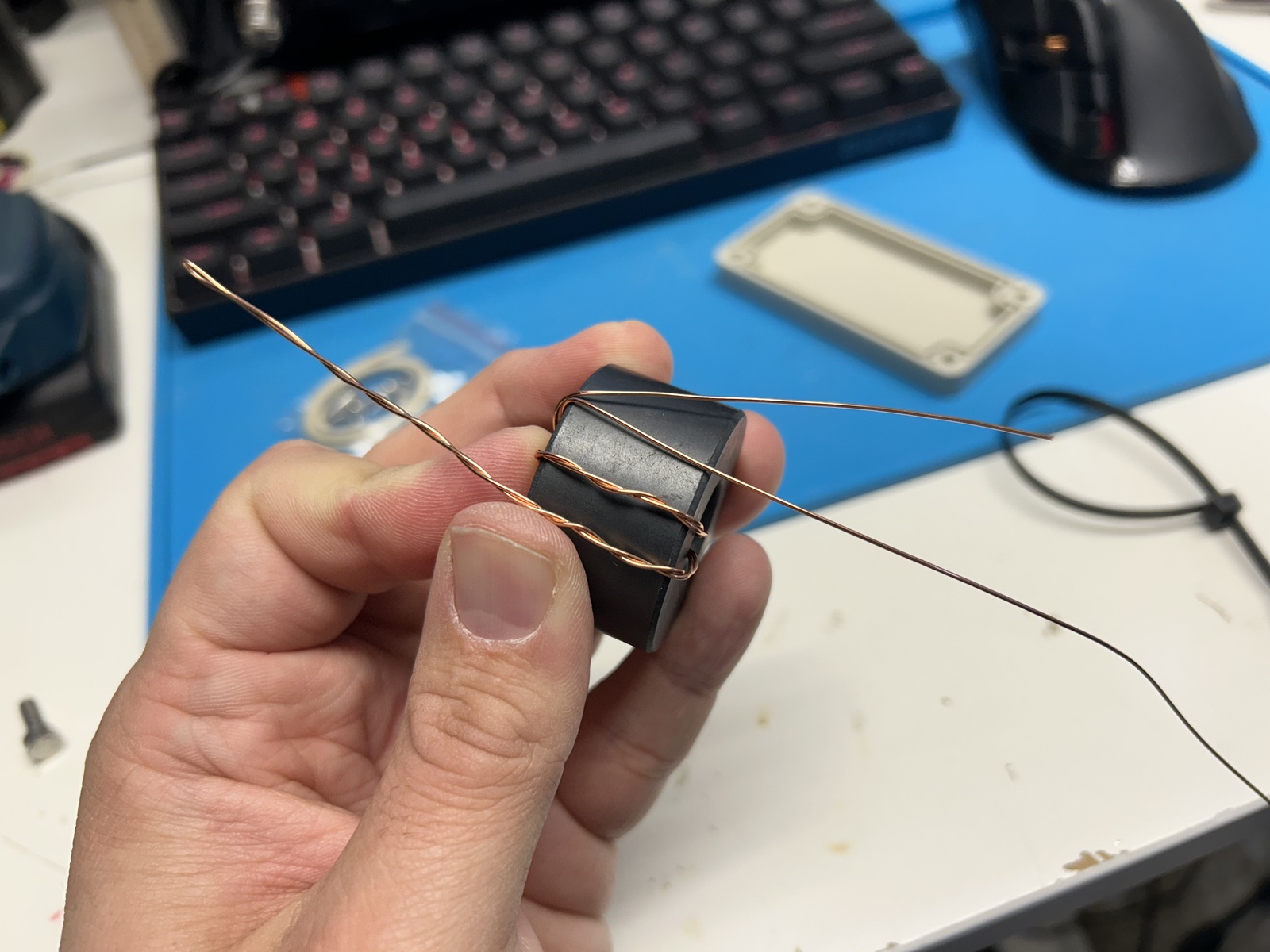
The next step is to begin winding the transformer. There are many resources online containing the details of exactly how they can be wound, and I hope that you find my photographs useful as well. In this instance I'm wrapping the transformer as a 56:1, with two primary turns and 15 secondary turns. I'm using 20 AWG (about 0.7mm) enamel coated magnet wire, about five or six feet. I have found this setup to be perfectly suitable for continuous use of digital modes at 100w, but you may want to use heavier gauge wire. Something I do like to do with these cores is use a zip tie (8" works well) around the circumference to lock the windings into place, otherwise they will have a tendency to slide around while you're building the rest of the enclosure. You will want to have a few inches of wire at each end free, and if you use a crossover winding for the 7th turn your transformer will have a "top" and a "bottom" which is useful for orienting in this kind of enclosure.

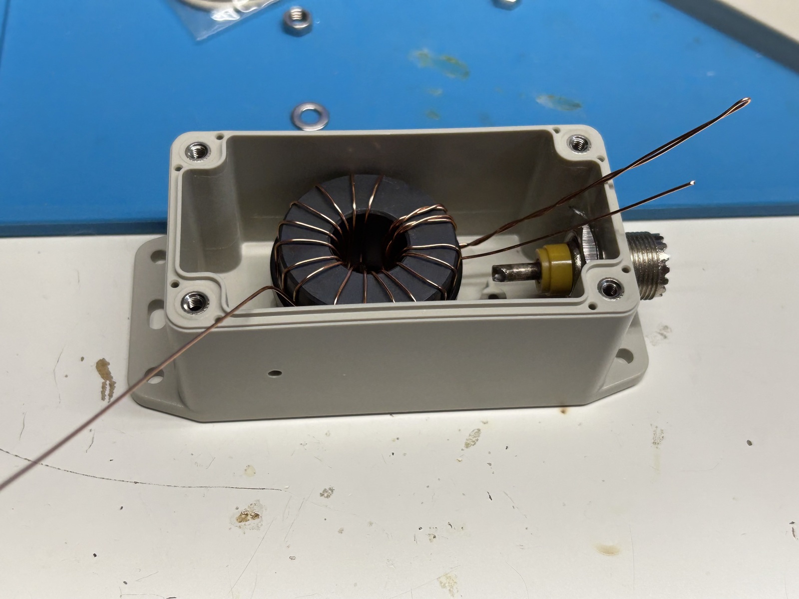
Once the core is wound you can place it in the box and begin figuring out how to trim and orient the leads.

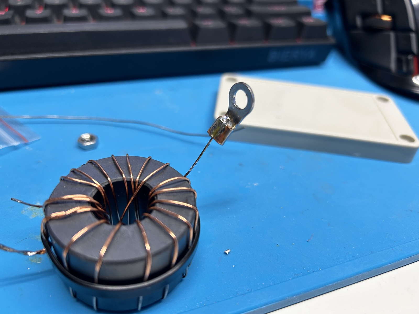
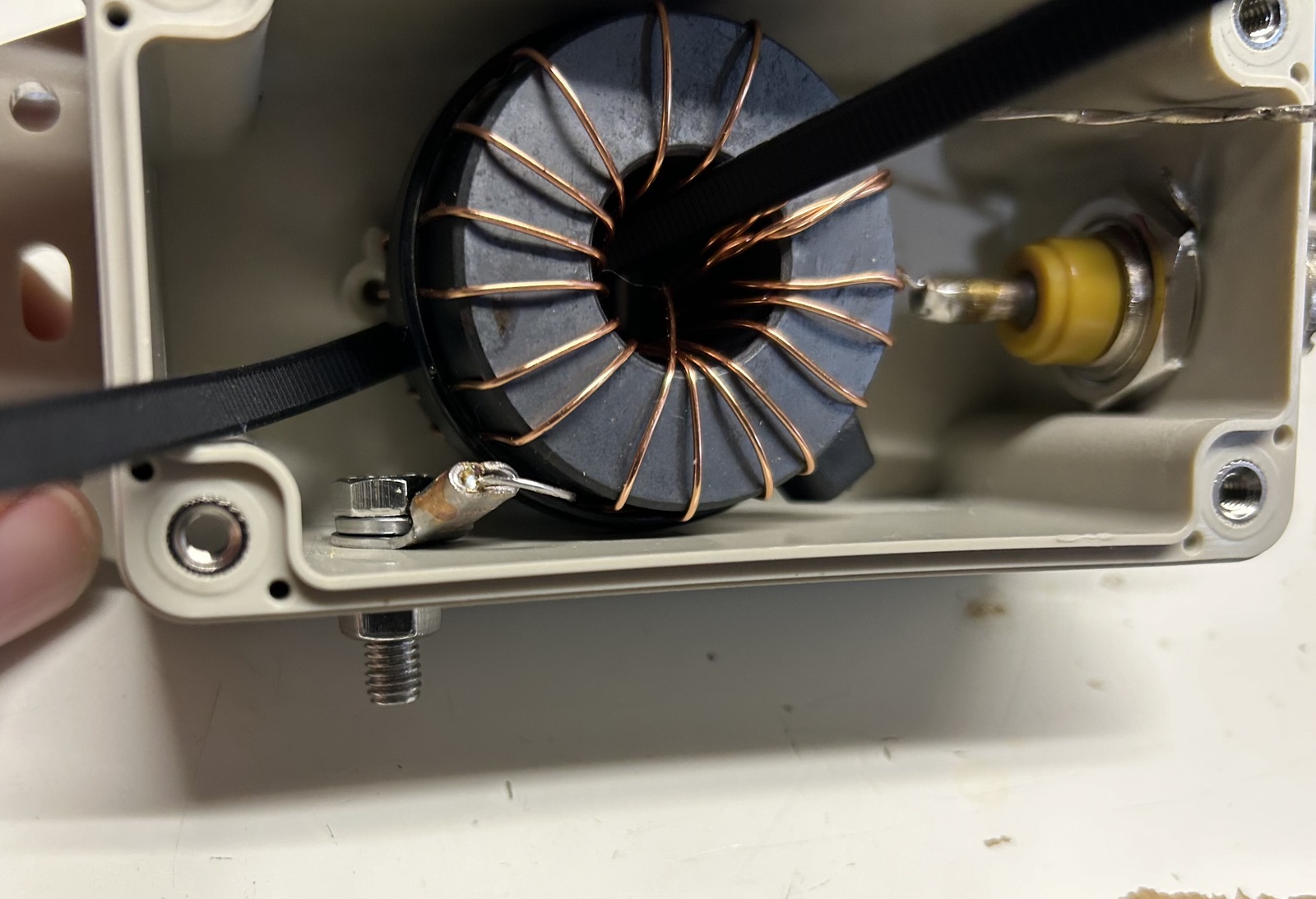
I used a 4mm ring terminal to terminate the antenna end of the transformer. Make sure to remove all of the enamel from the magnet wire before attempting to solder it!

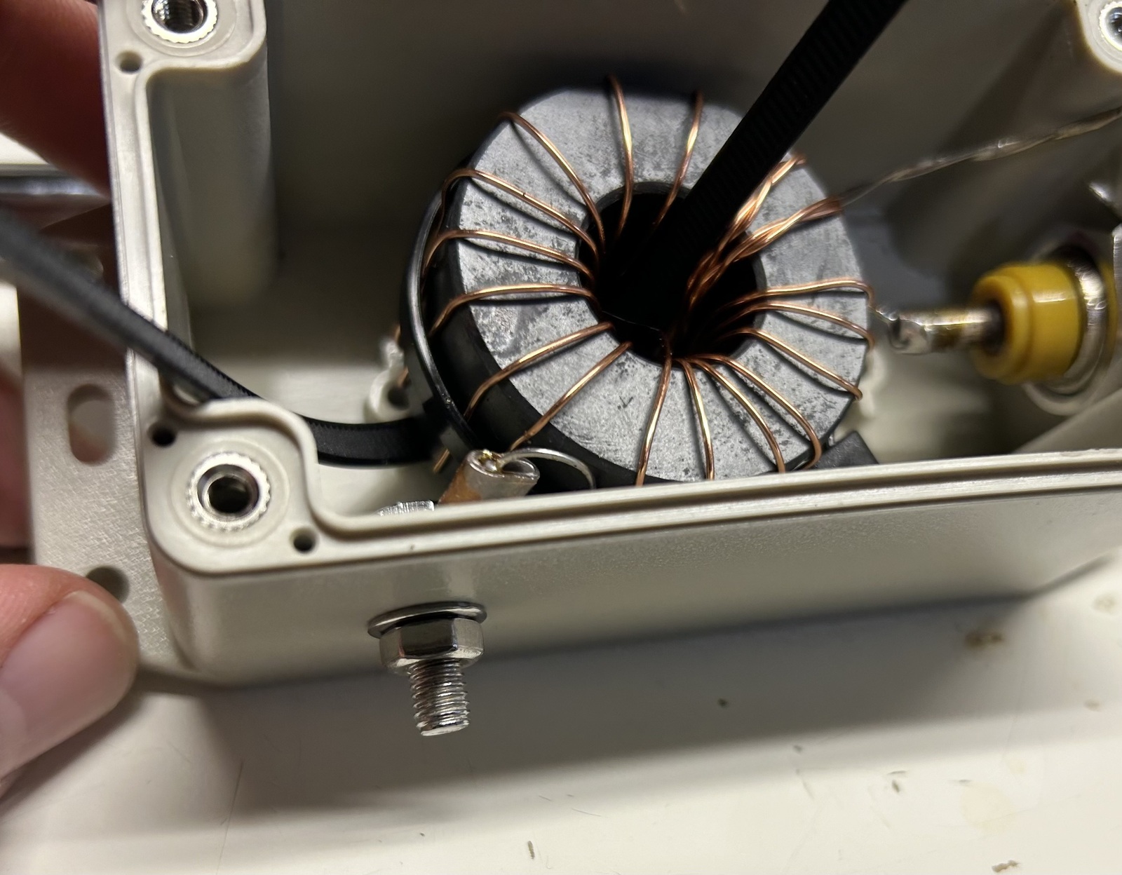
I passed a zip tie through the anchor plate and the center of the toroid, though I didn't tighten it. Once that was in place, I was able to trim and solder the other transformer wires to the SO-239 connector. Note that I have the antenna connection on the side of the box - this is in effort to prevent rain water from getting in.

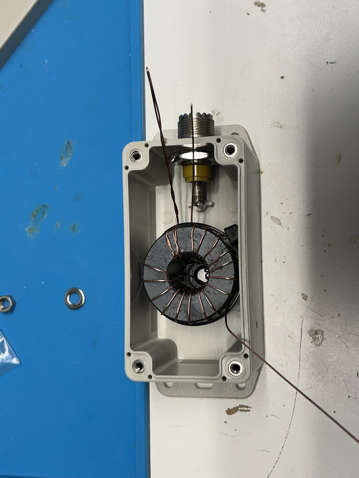
Next I installed the bolt that will be used to electrically connect the antenna to the transformer. The bolt I used was one I had on hand, and it is about 5-10mm too short for my liking - I may swap this out for a longer bolt in the future, but this one works fine. It's just a little short.

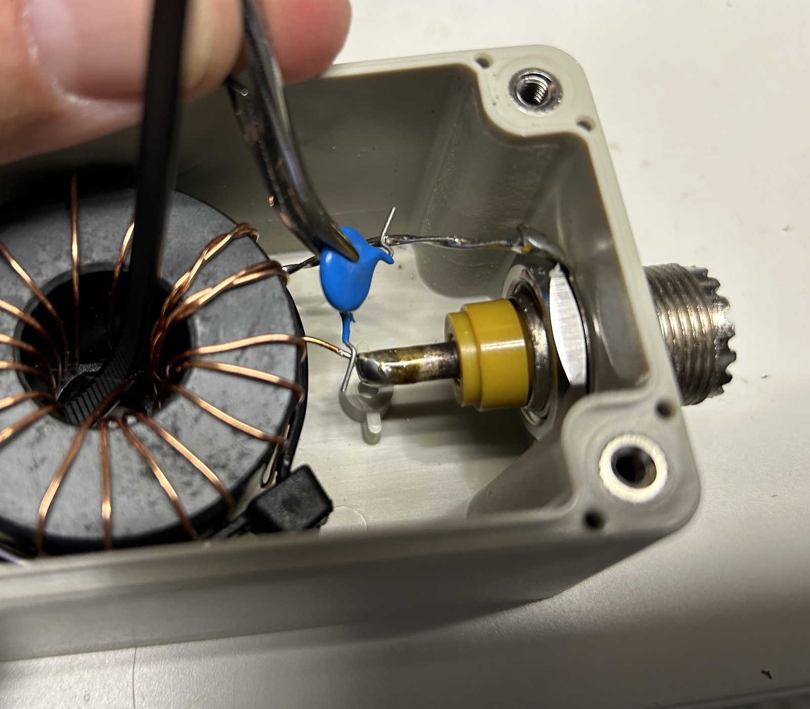
At this point, I completed the soldering to the shield of the coax connector, and added the capacitor. I went with a 120pF 3kV TDK cap, also from DigiKey. I have tested 80, 100, and 120pF caps in this position and haven't noticed a significant change between them. Some folks like to install a variable capacitor here to better tune the antenna, and I would like to try that at some point.

Many folks also add a lug for a counterpoise, which would electrically connect directly to the shield of the coax connector. In my installation I have not found a counterpoise to be necessary, but it's something to keep in mind.

Then it was time to tighten down the zip tie, add the gasket and some information to the underside of the lid, and button it up!

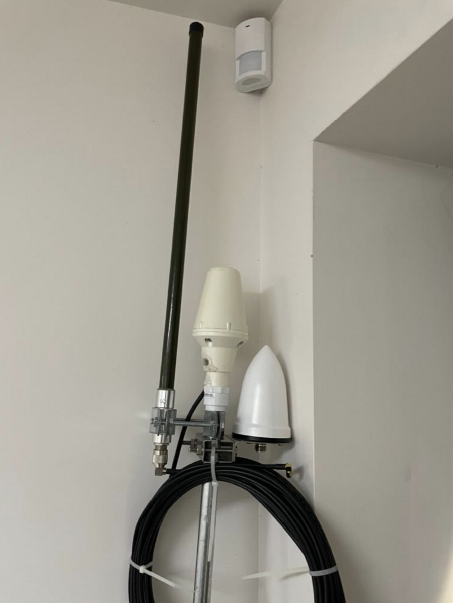
Installation was easy, simply drop the old transformer and haul up the new one.

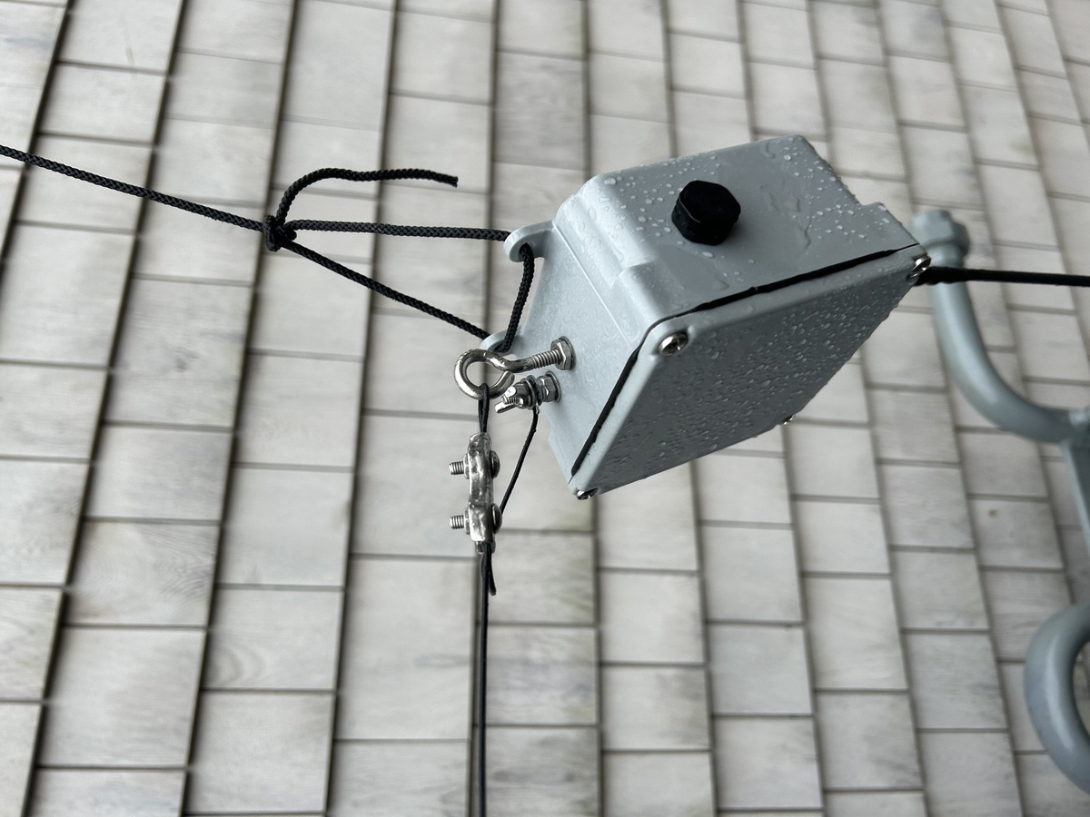
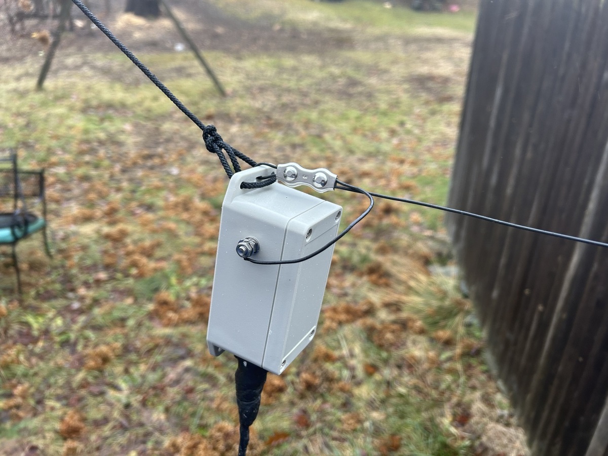
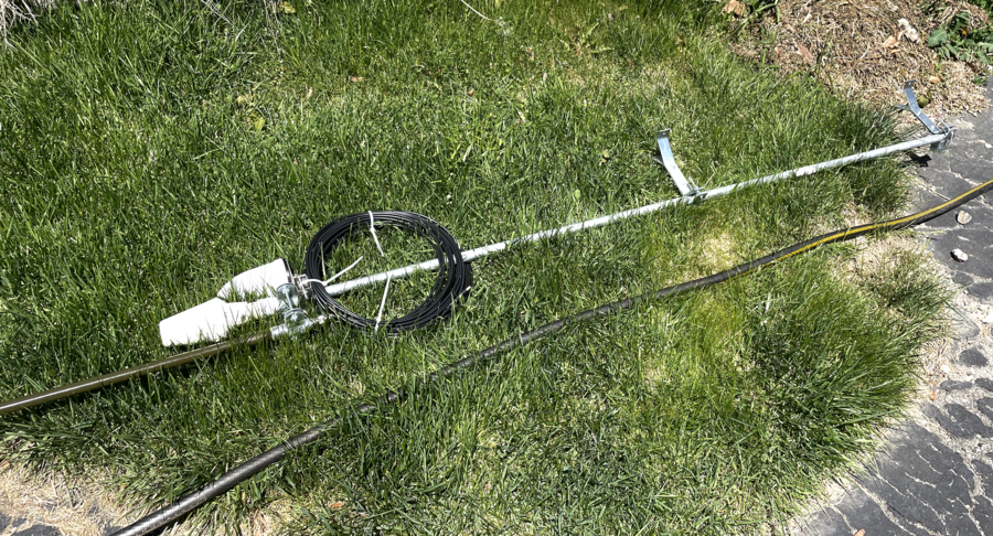
Here you can see how I have the hoist rope as well as the antenna wire looped through the tab at the top. Using a cable clamp on the antenna wire is critical as it removes strain from the antenna wire termination.

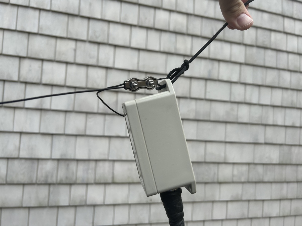
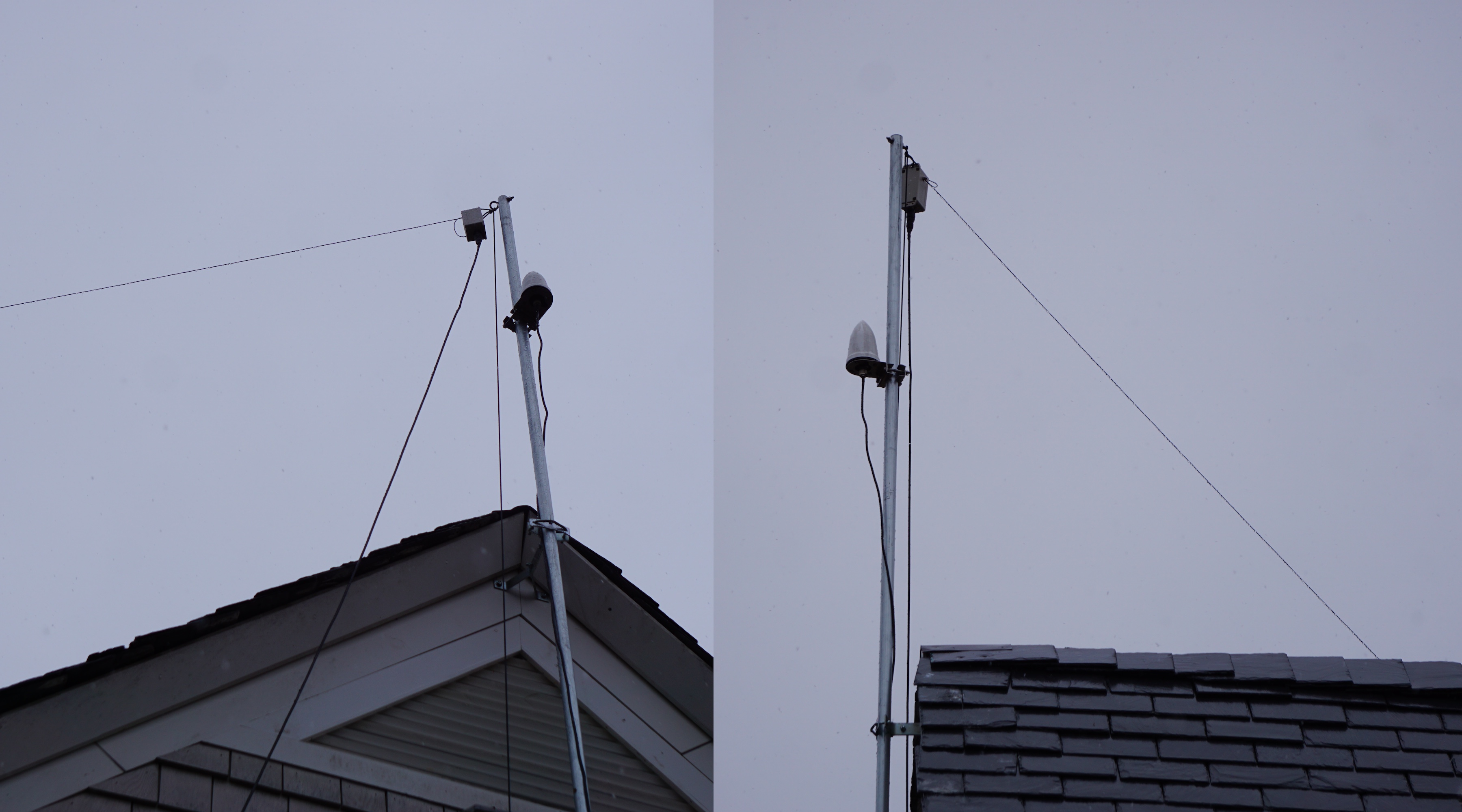
Hoisted up - seen from the front and the side. Optimally my feed line would be dropping straight down, but it's a few feet too short. It will be replaced with a run of N-terminated RG213 or similar sometime soon. I keep at least 100ft of rope, 1/8" Dacron, on either end of my antenna so that I can completely drop each end of the antenna to the ground at the same time, which makes maintenance and adjustments much easier.

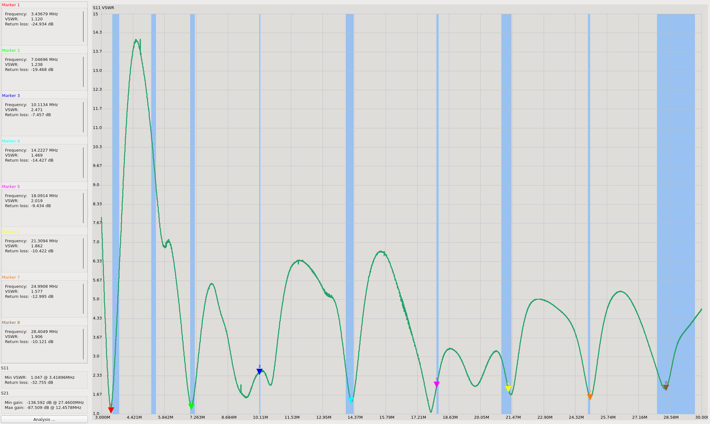
Here's the SWR plot from the NanoVNA. In my installation, with a 132ft wire, this antenna has a low enough SWR most of HF bands that it can be used without a tuner, and on the others (except for 60M) the "clean up" tuners present in many modern HF rigs can bring them to 1:1 with very little effort. Of course, low SWR is only part of the equation. Your environment and the characteristics of your installation play a major role in determining the antenna's effectiveness.

(Larger version here)

If you build one of these antennas and it works well for you, I would love to hear about it. If it doesn't work well for you, feel free to reach out and I can help you troubleshoot. Experimenting with antennas is one of my favorite parts of amateur radio, it is amazing to see what can be achieved with just a bit of wire and a toroid.

A final note - one potential downside to end fed antennas is that they tend to have a large amount of common mode current on the coax. Using them with a 1:1 choke is highly recommended. The chart on the following website is very helpful in determining an appropriate choke for the bands you intend to operate on as well as the materials you have. I use 12 turns of RG58 through an FT240-43, and am experimenting with other methods as well.

http://www.karinya.net/g3txq/chokes

Inexpensive GNSS Signal Splitter

Written by John Miller

GNSS receivers, like many other tools and pieces of equipment, have a tendency to replicate. Every time you turn around, there's another friendly timekeeping and position finding device on your desk, ready and waiting for some coax with some fresh GNSS signals. Unfortunately, well positioned antennas do not replicate as quickly as receivers do, so you may end up with windowsills lined with puck antennas - or worse, receivers that aren't doing anything at all!

While you, like me, may be able to put one or two antennas in a location that gets excellent sky view (up on your roof or a tower, for instance) choosing which receiver gets to connect directly to it is not an easy decision to make. Thankfully, there is a piece of technology that makes this decision a bit easier. If you read the title of this post, you may know that I'm talking about GNSS signal splitters. These are handy and fairly simple devices that split one antenna signal into two or more, allowing you to connect multiple GNSS receivers to one well positioned antenna. This is especially useful if you want to directly compare the performance of multiple GNSS receivers, or if you want to one or more units active for use in a project or another task, while the other connections on the splitter can be available for fiddling around with.

GNSS splitters tend to be very expensive, hundreds of dollars or more, because their purchasers tend to be industrial or commercial such that cost is no object - this makes things tricky for the hobbyist. One less expensive option that exists is the Time Machines Corp. splitter, which they sell a four port version of for $80. I have one of these units in our basement, and can confirm that it does work very well. The 3D printed case may turn off some folks, though, and while $80 is a lot less expensive than $400, it is still by no means "cheap".

I put two GNSS antennas on the roof a few months ago, with one running to the basement (into the aforementioned splitter) and the other running to the office. The latter of the two had no splitter at all, but while I mostly used it to tinker with, not having the ability to split the signal wasn't a huge deal - initially. Now, of course, I do want that capability, so I have to figure out a solution. Quite a while ago I came across the idea to get a normal RF splitter, which can be had for much less than a GPS-specific splitter, and modify it to be a GNSS splitter. Since I had hit a point where I wanted to hang multiple receivers off of the line coming into the office, I needed another splitter. Not wanting to spend another $80 on a Time Machines Corp. splitter, I decided to poke around a bit more at the DIY route.

Before I go too much further, I should take a moment to explain the difference between an "RF splitter" and a "GNSS splitter". GNSS signals are, of course, RF, so this may be a differentiation that makes little sense - but there is one important difference. Many RF splitters on the market are actually RF splitter/combiners, which means they can be used for both receiving and transmitting. Their construction is usually fairly simple - one RF connector with its signals being divided amongst multiple other connectors (or, conversely, multiple connectors being combined into one, depending on how you look at it). Depending on their rated frequency range and power handling characteristics, their actual construction can be quite nuanced, but generally speaking you have inductors (either as discrete components or PCB traces) to provide filtering, and resistors, to keep the circuit balanced. What they often don't have, however, are DC blocking capacitors. The crucial component to turn a generic RF splitter into a GNSS splitter.

GNSS receivers, as the name implies, do not transmit RF - they only receive the data transmitted from GNSS satellites. Often, however, they do put DC voltage on the center conductor of the coax specifically to power the low noise amplifier contained within the GNSS antenna. This setup is not ubiquitous, but it is very common, especially with more modern GNSS receiver configurations. The signals transmitted by GNSS satellites are very low power, and as such it is very common to build a low noise amplifier, or LNA, directly onto the receiving antenna to help boost signals that might otherwise be drowned out by local interference, or that might be very low on horizon. These LNAs are often powered by 3 to 5v DC (sometimes as high as 12v) and they greatly increase the effectiveness of GNSS receivers. Some GNSS receivers have external circuitry for powering and monitoring these LNAs, and in some configurations the LNA is part of the receiver itself, rather than being part of the antenna. The power drawn by the LNA is very low, tens of milliamps on newer antennas, something discrete GNSS receivers can easily handle.

What GNSS receivers can not handle, however, is having other DC voltages pushed into them. I have read multiple accounts of individuals connecting a handful of GNSS receivers to a plain RF splitter only to have them all fail within a minute or two because their front ends were blown out by DC injected by their neighbors. In some receivers it is possible to disable this DC output in software, but you have to be very careful - outside DC coming in can still blow them out. This scenario is what differentiates RF splitters from GNSS splitters. This is what the DC blocking capacitors are for.

Capacitors are transparent to AC (RF) but will block DC in both directions - to a point, anyway. For the low voltages and amperages involved here, they are an excellent solution to the GNSS splitting problem. The typical configuration is as follows: one port along the splitter does not get a DC block fitted to it - this port is connected to the one receiver that will power the LNA in the antenna. The rest of the ports in the splitter have capacitors positioned in line with the incoming RF. The amplified signal coming down from the antenna's LNA to each of those ports is able to easily traverse the capacitors, but the DC voltage coming up from those receivers is stopped by them, preventing either the LNA or the other receivers' front ends from being overloaded. In some cases, a resistor to ground is needed between the receiver and the blocking capacitor in order to put some load on the LNA-powering circuit of the receiver. This is sometimes required because some receivers will declare a fault condition if they don't see any current being pulled by the antenna's LNA. A valid concern, but not particularly relevant in this case. The receivers that I have primarily tested and worked with can be configured to complain about this condition, but do not do so by default.

So now that you've made it this far, and you understand why these devices exist and what sets them apart from "normal" RF splitters, I'm going to explain what I actually did. As I mentioned above, I have been thinking about getting my hands on another splitter for a while now, and as such I would periodically check ebay for good options to work with. Last week I found a listing for a four-way Meca power splitter/combiner, 0.8-3GHz, listed at $0.99. A perfect candidate for this project. To my pleasant surprise, I won it for $1.25 - go figure. Even if you can't find one that cheap, I regularly see similar devices for sale for $30 or less. These are absolute "jellybean" components in the RF world and the secondhand market is absolutely rife with them.

When it arrived and I popped the lid, I was very pleased to see a very tidy device with an uncoated FR4 PCB and copper traces without solder mask, making the required modification very easy. My plan was to leave the leftmost connector as the "DC passthrough" connector, and then the three to the right would have the blocking capacitors fitted. The only reason for this decision was to match the layout of my other GNSS splitter - any of the four ports could be used as the bypass port.

The first step in the modification was to cut the trace between the second connector and the rest of the circuit. I achieved this, somewhat messily, with a small flatblade screwdriver. A very small dremel or similar tool might be cleaner, but since this was uncoated copper on bare FR4 it was very easy to remove. Use an ohmmeter to verify that the copper is completely removed.

The next step is to mount your DC blocking capacitor across the copper traces to reconnect it with the rest of the circuit. I used an 0805 10nF ceramic capacitor. Before you do the other two connectors, this is a good opportunity to test it out. Attach a GNSS receiver that you know outputs voltage for an LNA, and measure that voltage on the antenna connector. Measure for that voltage one the second connector - there shouldn't be any. If this is the case, connect a second receiver and verify that it works as expected.

On the other side, the procedure was slightly different. I removed the bottom-most resistor in the chain, then cut out the copper between the traces and the pads that ran to each connector. Again, verify that these traces are completely removed.

Next, I soldered in two more capacitors across each of the breaks.

At this point, test the rest of the connectors and verify their operation. I had four receivers going on this splitter and each reporting many SVs with an SNR of over 40.

Finally, no project is complete without a slightly off-center label.

This was a fun and easy project that cost me less than $10 all in. Even if I had to buy a splitter at $30 it would have been well worth it. There are a lot of ways you could implement something like this yourself, as there are many different designs of RF splitters out there, not to mention different blocking capacitor values to try, as well as adding bleed resistors to trick the LNA-power monitors into thinking they are doing something.

I hope you found this post beneficial or at least interesting, and I'd love to hear from you either way!

Antennas on the Roof

Written by John Miller

I have been into electronics my whole life, and radio most of it. I got my amateur radio license early in my 20s, and while I haven't been super active on the communication side of things, I do try and keep up with the technology. Sometime in the early 2010s, when it was discovered that cheap USB digital TV receivers could be used as wide band software defined radios, I dug hard into that. Listening in on ham bands, commercial and public safety traffic, pulling down weather satellite images, and decoding aircraft transponders, among other things.

I have always been into GPS as well, but only recently did I really dig into it for anything other than positioning. I knew that GPS-disciplined clocks existed, but always assumed that they were well beyond my scope.

Receiving and decoding aircraft transponder signals, ADS-B/MLAT has long since been one of my favorite applications of these USB SDRs due to its intersection of radios, aircraft, and GIS. The data coming out of ADS-B systems is very useful for working with real time GIS systems, but realistically, it's just plain cool.

The trick is that ADS-B transmits at 1090MHz, high enough frequency to get disrupted by pretty much anything - structures, trees, roofs, etc. On top of that, the signals broadcast from the aircraft aren't particularly powerful, so you really want a high gain antenna and a wide-band filter to cut out as much as you can. Thankfully, both of these things are generally available and neither are particularly expensive. The tricky part, as it figures, is getting the antenna up in the air.

In college, when I first got into this, I had lots of space and the airwaves were fairly quiet (rural area) so it worked well. The next place we lived I hung an antenna in the attic, and the performance was pretty rough - the place after that was the same. The apartment we lived in after that, we had a balcony on the third floor, so while it worked well, everything behind the antenna, or about 200º worth of azimuth, was entirely masked by the rest of the building.

Where we are now is pretty RF-quiet, and we have a house that's well suited for putting an antenna mast up, about 30ft off the ground. Not incredibly high, but high enough to get over the built environment and get a full sweep of coverage. So all there is to do is rig it up. Only putting up an ADS-B antenna would be a waste of a mast, though, so it's a good thing that over the past couple of years I've picked up GPS timekeeping as a hobby.

Most of the time, a decent GPS puck antenna hanging off a modern sensitive receiver will work just fine sitting on a windowsill. This is what I recommend for folks interested in running a TimeHat out of their home. I wanted to scale up from that for my own setup for a few reasons. First is simply because I have the means to - I already have a few high-gain reference/timing antennas with brackets, and I'm putting up the mast anyway - adding two reference antennas isn't going to cause any problems. Second, I want to use a few older receivers that really need a high gain signal: Trimble Thunderbolt and Copernicus II, True Position GPSDO, some older hopf gear, etc. All are capable and suitable pieces of equipment, but they are limited to 8 or 12 channels, GPS only, so a puck antenna in a windowsill often is only going to cut it for a few hours a day. Finally, I want to run these antennas into four or six way splitters, so I want as much gain coming out as possible.

mast setup

This is the completed setup. The only component I didn't already have was the standoff bracket for the ADS-B antenna. One reference antenna is directly on top of the mast, and the other is offset slightly just beneath it. This isn't a completely optimal situation, because the GPS antennas could possibly mask each other slightly, but this is really a non-issue. The issue is getting it up on the roof.

mast ground

I had that mast assembled and parked in the basement for a few months before putting it up. A combination of factors held up that step - timing, weather, and, of course, the actual "how" of getting the thing hauled up 30ft and mounted to the side of the house. In the photo above, all that is shown is the top of the mast. The mast itself is a six foot long piece of half inch steel tube, and on the bottom and about four feet up are two brackets that stand it off about six inches from the side of the house. The top bracket attaches to the peak of the roof, and the bottom one attaches to the top of the window frame.

I eventually decided on the tried and true fiberglass extension ladder for my method of going up. I looked into hiring help or renting a lift or something, but those options were prohibitively expensive. Renting a 32 foot ladder from home depot was only about $50, plus about $40 to buy a ladder stabilizer to offset it sufficiently from the side of the house, and of course provide some additional stability for me.

car ladder

Frankly one of the most difficult parts of the whole process was standing the ladder up against the side of the house. Between my wife and myself we managed, but it wasn't quick and easy. The ladder with the stabilizer was probably only about 70-80lbs, but when that's a 30-some foot lever swinging around in the air, things get interesting.

I didn't get any pictures of the mounting process when I was up there, but there's really not a whole lot to say. I wasn't entirely certain how I was going to actually get the mast up there with me. Initially I suppose I figured that I was going to carry it up with me, but after the first time going up the ladder it was clear that wasn't going to be a realistic option, simply due to the fact that it was too heavy and the mounting brackets would get caught on the rungs of the ladder. What I settled on, much more reasonably, was dropping a rope over the ladder stabilizer, tying it off on the mast (at the bottom and top, so it would come up straight), then climbing up to the top and pulling it up. There I could relatively easily brace it into position and drive in the lag bolts.

house ladder

There are three coaxial cables coming off, one GPS antenna is running down the front roof edge where it then drops down along the street power conduit, then pops into the basement, feeding the GPS receivers on the rack. The other GPS and ADS-B lines run into the eave vent and then drop through the ceiling right there into my office.

There's also a heavy bare copper wire (6ga, I think) clamped to the mast, running down the same path as the line going to the basement. Rather than going to the basement it's terminated as a proper grounding stake underneath our power meter.

house mast 
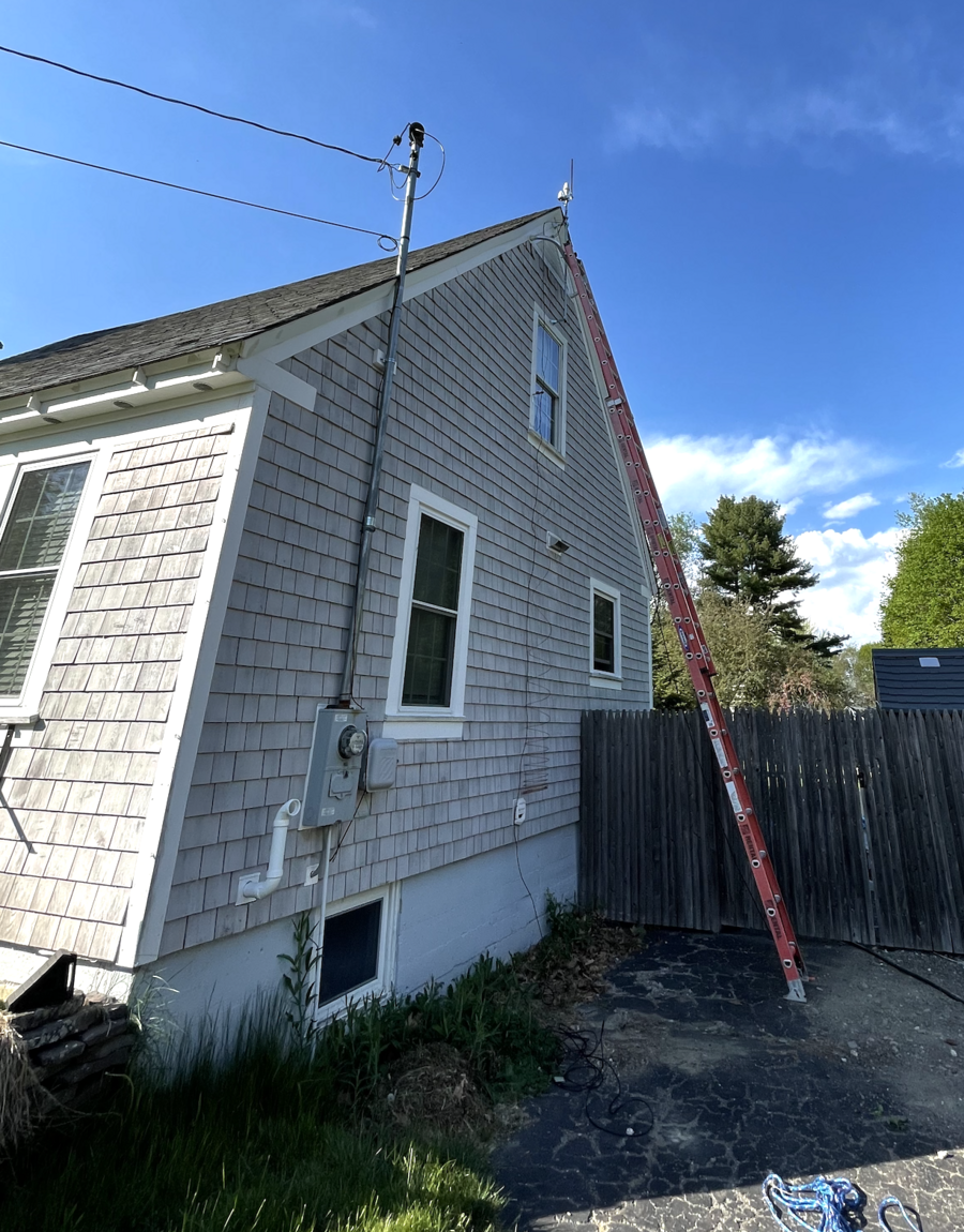
(Yes, I know a few siding shingles are missing up there, it's not a big deal.)

So, how does this setup perform? Well, it performs great. Satellite coverage for both antennas is incredible - there's a hole over the north pole, of course, but now that the antennas are up over the roof line there is great visibility to the south.

gpsd stats

ADS-B varies, of course, given the number of aircraft currently in the air. Coverage is impressive, however, most of Maine excluding the Portland area, and well into New Brunswick. The greatest range that I've seen so far has been about 200 miles, to an airliner at about 40,000ft over the Atlantic, off the coast of Massachusetts.

adsb stats

Quicksilver PSU Fan Replacement

Written by John Miller

Most PowerMac G4s are about 20 years old now, which means they all need some degree of work to run as well as they did when they were new. Fans are one of the most common replacements needed, and in most G4s, the fan in the power supply is the first to go. This post exists to serve as a basic guide for how to replace that fan. In the case of my Quicksilver, it is a standard 80mm x 80mm x 25mm PC fan. I used a part pulled from a few-years-old office PC. It's worth noting that the it only needs power and ground, PWM and sense lines on most modern fans are not connected at all. In my case, I cut them off.

To start, power off the machine and open it. I removed the HDD carriers to give a bit more space.

one

Remove the optical drive carrier. There are four screws, two at the top, one underneath, and one on the front panel. These screws are the same. It will take some wiggling to get it to come out, and expect the power cables to be VERY stiff if they haven't been removed before.

two

Now remove the bracket behind the PSU. Three screws, two behind the PSU and one under it. The bracket will pop straight out. After that, remove the big 120mm fan (don't forget to disconnect its power source!) There are two large screws with big flat heads holding it in, one is holding down a black plastic cable wrap, the other is under the fan. The fan will kind of drop out once this is done.

Next comes the rear PSU screws. These are three 2.5mm hex screws. Once removed, the PSU can be slid backwards and then tipped into the case. Once tipped into the case, feed the power cables up through the opening in the horizontal bracket.

With the chassis being nice and empty, this is a good opportunity to clean out any dust that may have accumulated.

Now that the PSU is out, we can disassemble it and replace the fan. Taking it apart is very easy - four screws right on top, then the top metal case will lift straight off. All standard precautions regarding working in AC voltage equipment apply. If you want to be extra safe, wait a day with the PSU completely disconnected to allow the capacitors to discharge completely.

PSU fan area

In this picture you can see that I've already pulled out the fan, and I've also cut out the metal grille at the back of the power supply - more on that in a moment. Removing the fan is trivial. Unscrew the two screws at the rear holding it in, move the blue and brown AC cables routed above it (you may need to snip a cable tie and pop the ferrite bead off of the fan), disconnect the fan's power connector, then push the rear of the metal PSU casing outwards in order to slide the old fan up and out. This is also a good opportunity to clean up the dust that has accumulated within the PSU.

If your new fan has a similar type of connector, swapping the old one should be easy. Use a small pin or screwdriver to push down the locking tabs on the metal bit on the back, and slide out the wire with the metal springy bit. Do this to remove the connector from the old fan and swap it onto the new fan and you should be all set. Otherwise, I'm going to leave the process of connecting the new fan up to the reader.

Looking at the rear of the PSU, with the metal grille snipped out. Why? Well, most computers expose this grille to the world, whereas in the G4 it is hidden behind yet another plastic grille. This double-grille creates additional noise, and it's a lot cleaner looking to remove the grille from the power supply than it is to remove from the rear plastic of the machine. If you're not sure about this, don't do it! Test the machine with a new PSU first, and if it's not noisy - leave it alone. If it seems a bit too noisy, remove it.

At this point, you're finished. Put the PSU back together and re-assemble the machine.

More TimeHats!

Written by John Miller

Back in April of this year, a renewed interest on the Time Nuts mailing list developed regarding my TimeHats. The first run of them back at the beginning of the year was fairly small, only 20 units, and only about 15 of them went to folks on the TimeNuts list. They developed a good reputation and I received some very positive public feedback - prompting more interest. I posted saying that I hadn't planned on making more than those initial 20, but that I hadn't yet developed a new revision, so if people were interested I could do another run of identical units, I just needed to know how many parts to order.

The interest ended up being more significant than I had anticipated. A lot more! To the tune of about 150 as it stands today. Due to the current global parts shortage I decided against taking any kind of pre-orders (though it would have helped financially) because I didn't know if I would run into any issues delivering units. At the moment I am waiting for the second big delivery of GPS receivers and antennas - 100 in total. I have already assembled, tested, and shipped about 50 units.

I took a number of pictures along the way as I have assembled them, so I wanted to post them here as a sort of "photo essay".

The first parts to arrive were the µSD cards, 70 of them.

Next up were the PCBs and RTC modules, as well as other little odds and ends like batteries, screws, standoffs, etc.

There's lots of processing that needs to be done, lots of intermediary steps. The holes in the PCBs are slightly too small for my M3 screws, so they have to be drilled out a big larger (I do this with stacks of boards, so it goes fairly quickly). The headers from both the RTC modules and GPS modules need to be removed, and in the case of the GPS modules, the holes must be clean and clear as they are re-used - in the case of the RTC modules we use the second header that is available.

Going with full-size 40 pin headers was a mistake, even though I got them very cheap. They took FOREVER to solder. The next go around I will use much smaller headers that only use the pins I need - in this case it's only a small handful clustered at the top.

Before the modules could be soldered onto their boards, they had to be tested, so I added two female headers to a PCB to make testing quick. A great thing about both of these modules is that they can be fully tested without rebooting the whole system, meaning testing is relatively fast.

Next, it was time to start assembling! This went pretty quickly.

And before long I had 97 boards waiting for GPS modules.

It took a while, but the GPS modules and antenna finally showed up! (And I'm still waiting for more.....)

Then they needed the same testing and processing as the RTCs did.

With both modules installed, proper testing could commence. This took a while.

But once completed, they got parked in the box and are ready to ship!