Inexpensive GNSS Signal Splitter
GNSS receivers, like many other tools and pieces of equipment, have a tendency to replicate. Every time you turn around, there's another friendly timekeeping and position finding device on your desk, ready and waiting for some coax with some fresh GNSS signals. Unfortunately, well positioned antennas do not replicate as quickly as receivers do, so you may end up with windowsills lined with puck antennas - or worse, receivers that aren't doing anything at all!
While you, like me, may be able to put one or two antennas in a location that gets excellent sky view (up on your roof or a tower, for instance) choosing which receiver gets to connect directly to it is not an easy decision to make. Thankfully, there is a piece of technology that makes this decision a bit easier. If you read the title of this post, you may know that I'm talking about GNSS signal splitters. These are handy and fairly simple devices that split one antenna signal into two or more, allowing you to connect multiple GNSS receivers to one well positioned antenna. This is especially useful if you want to directly compare the performance of multiple GNSS receivers, or if you want to one or more units active for use in a project or another task, while the other connections on the splitter can be available for fiddling around with.
GNSS splitters tend to be very expensive, hundreds of dollars or more, because their purchasers tend to be industrial or commercial such that cost is no object - this makes things tricky for the hobbyist. One less expensive option that exists is the Time Machines Corp. splitter, which they sell a four port version of for $80. I have one of these units in our basement, and can confirm that it does work very well. The 3D printed case may turn off some folks, though, and while $80 is a lot less expensive than $400, it is still by no means "cheap".
I put two GNSS antennas on the roof a few months ago, with one running to the basement (into the aforementioned splitter) and the other running to the office. The latter of the two had no splitter at all, but while I mostly used it to tinker with, not having the ability to split the signal wasn't a huge deal - initially. Now, of course, I do want that capability, so I have to figure out a solution. Quite a while ago I came across the idea to get a normal RF splitter, which can be had for much less than a GPS-specific splitter, and modify it to be a GNSS splitter. Since I had hit a point where I wanted to hang multiple receivers off of the line coming into the office, I needed another splitter. Not wanting to spend another $80 on a Time Machines Corp. splitter, I decided to poke around a bit more at the DIY route.
Before I go too much further, I should take a moment to explain the difference between an "RF splitter" and a "GNSS splitter". GNSS signals are, of course, RF, so this may be a differentiation that makes little sense - but there is one important difference. Many RF splitters on the market are actually RF splitter/combiners, which means they can be used for both receiving and transmitting. Their construction is usually fairly simple - one RF connector with its signals being divided amongst multiple other connectors (or, conversely, multiple connectors being combined into one, depending on how you look at it). Depending on their rated frequency range and power handling characteristics, their actual construction can be quite nuanced, but generally speaking you have inductors (either as discrete components or PCB traces) to provide filtering, and resistors, to keep the circuit balanced. What they often don't have, however, are DC blocking capacitors. The crucial component to turn a generic RF splitter into a GNSS splitter.
GNSS receivers, as the name implies, do not transmit RF - they only receive the data transmitted from GNSS satellites. Often, however, they do put DC voltage on the center conductor of the coax specifically to power the low noise amplifier contained within the GNSS antenna. This setup is not ubiquitous, but it is very common, especially with more modern GNSS receiver configurations. The signals transmitted by GNSS satellites are very low power, and as such it is very common to build a low noise amplifier, or LNA, directly onto the receiving antenna to help boost signals that might otherwise be drowned out by local interference, or that might be very low on horizon. These LNAs are often powered by 3 to 5v DC (sometimes as high as 12v) and they greatly increase the effectiveness of GNSS receivers. Some GNSS receivers have external circuitry for powering and monitoring these LNAs, and in some configurations the LNA is part of the receiver itself, rather than being part of the antenna. The power drawn by the LNA is very low, tens of milliamps on newer antennas, something discrete GNSS receivers can easily handle.
What GNSS receivers can not handle, however, is having other DC voltages pushed into them. I have read multiple accounts of individuals connecting a handful of GNSS receivers to a plain RF splitter only to have them all fail within a minute or two because their front ends were blown out by DC injected by their neighbors. In some receivers it is possible to disable this DC output in software, but you have to be very careful - outside DC coming in can still blow them out. This scenario is what differentiates RF splitters from GNSS splitters. This is what the DC blocking capacitors are for.
Capacitors are transparent to AC (RF) but will block DC in both directions - to a point, anyway. For the low voltages and amperages involved here, they are an excellent solution to the GNSS splitting problem. The typical configuration is as follows: one port along the splitter does not get a DC block fitted to it - this port is connected to the one receiver that will power the LNA in the antenna. The rest of the ports in the splitter have capacitors positioned in line with the incoming RF. The amplified signal coming down from the antenna's LNA to each of those ports is able to easily traverse the capacitors, but the DC voltage coming up from those receivers is stopped by them, preventing either the LNA or the other receivers' front ends from being overloaded. In some cases, a resistor to ground is needed between the receiver and the blocking capacitor in order to put some load on the LNA-powering circuit of the receiver. This is sometimes required because some receivers will declare a fault condition if they don't see any current being pulled by the antenna's LNA. A valid concern, but not particularly relevant in this case. The receivers that I have primarily tested and worked with can be configured to complain about this condition, but do not do so by default.
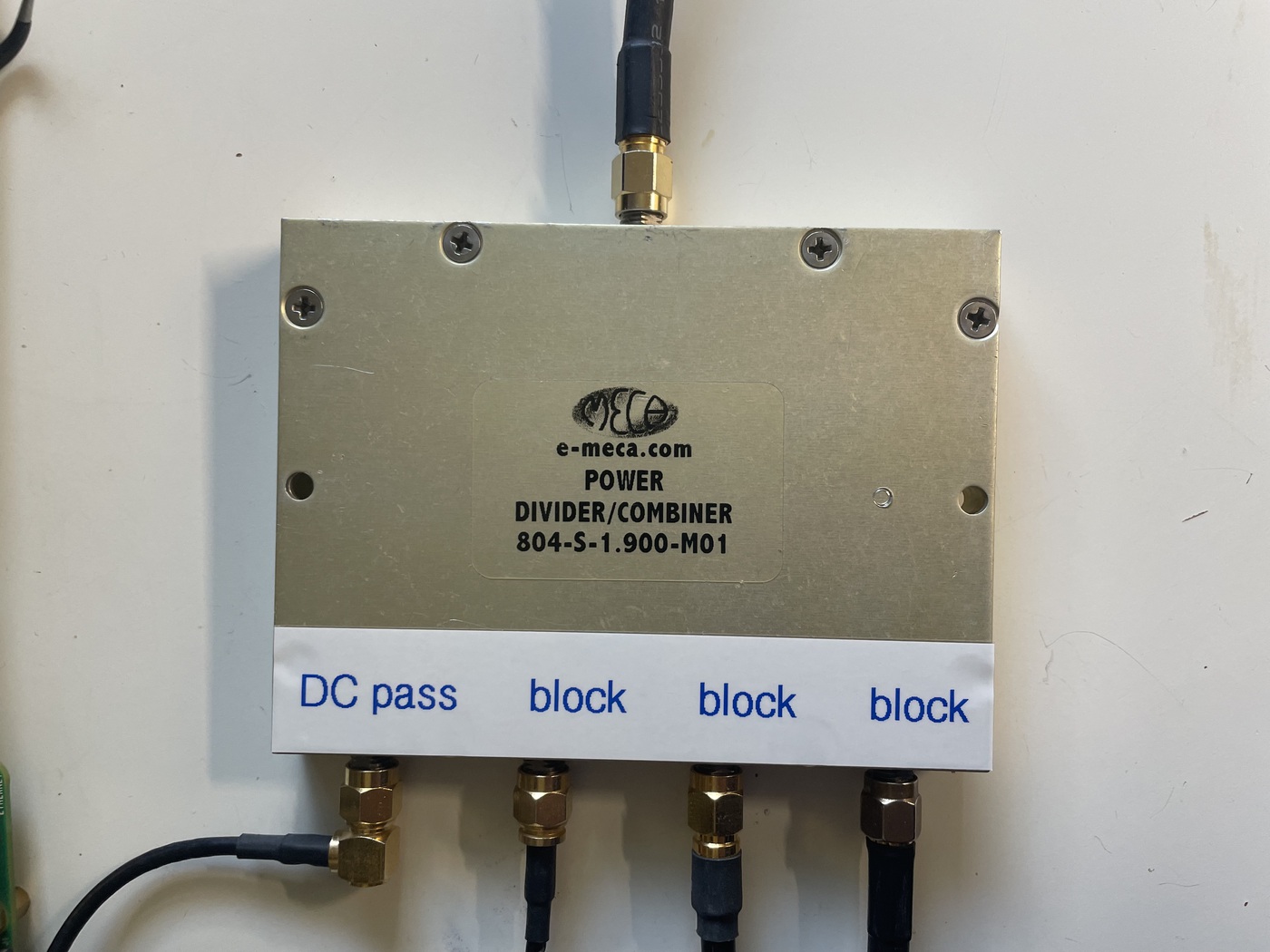
So now that you've made it this far, and you understand why these devices exist and what sets them apart from "normal" RF splitters, I'm going to explain what I actually did. As I mentioned above, I have been thinking about getting my hands on another splitter for a while now, and as such I would periodically check ebay for good options to work with. Last week I found a listing for a four-way Meca power splitter/combiner, 0.8-3GHz, listed at $0.99. A perfect candidate for this project. To my pleasant surprise, I won it for $1.25 - go figure. Even if you can't find one that cheap, I regularly see similar devices for sale for $30 or less. These are absolute "jellybean" components in the RF world and the secondhand market is absolutely rife with them.
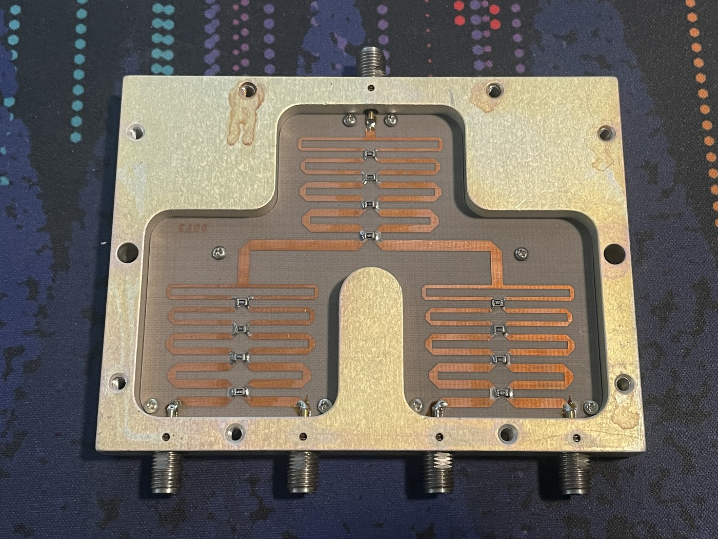
When it arrived and I popped the lid, I was very pleased to see a very tidy device with an uncoated FR4 PCB and copper traces without solder mask, making the required modification very easy. My plan was to leave the leftmost connector as the "DC passthrough" connector, and then the three to the right would have the blocking capacitors fitted. The only reason for this decision was to match the layout of my other GNSS splitter - any of the four ports could be used as the bypass port.
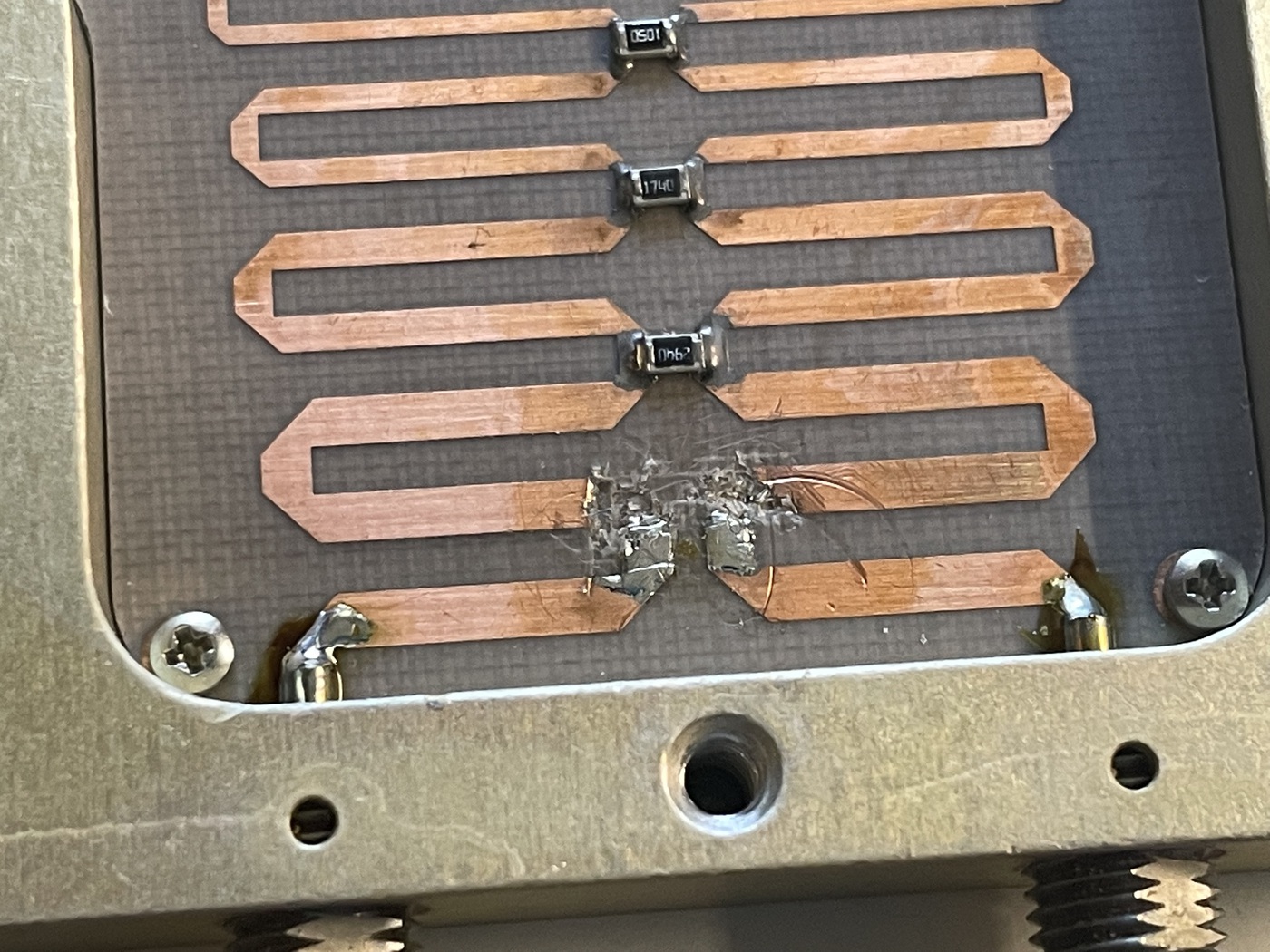
The first step in the modification was to cut the trace between the second connector and the rest of the circuit. I achieved this, somewhat messily, with a small flatblade screwdriver. A very small dremel or similar tool might be cleaner, but since this was uncoated copper on bare FR4 it was very easy to remove. Use an ohmmeter to verify that the copper is completely removed.
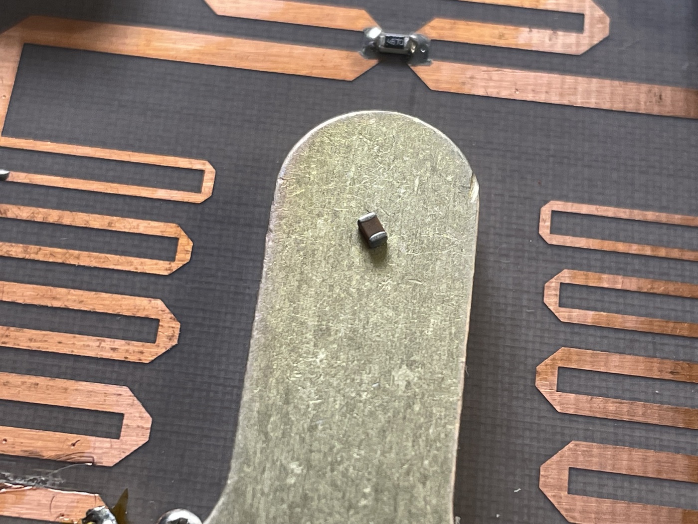
The next step is to mount your DC blocking capacitor across the copper traces to reconnect it with the rest of the circuit. I used an 0805 10nF ceramic capacitor. Before you do the other two connectors, this is a good opportunity to test it out. Attach a GNSS receiver that you know outputs voltage for an LNA, and measure that voltage on the antenna connector. Measure for that voltage one the second connector - there shouldn't be any. If this is the case, connect a second receiver and verify that it works as expected.
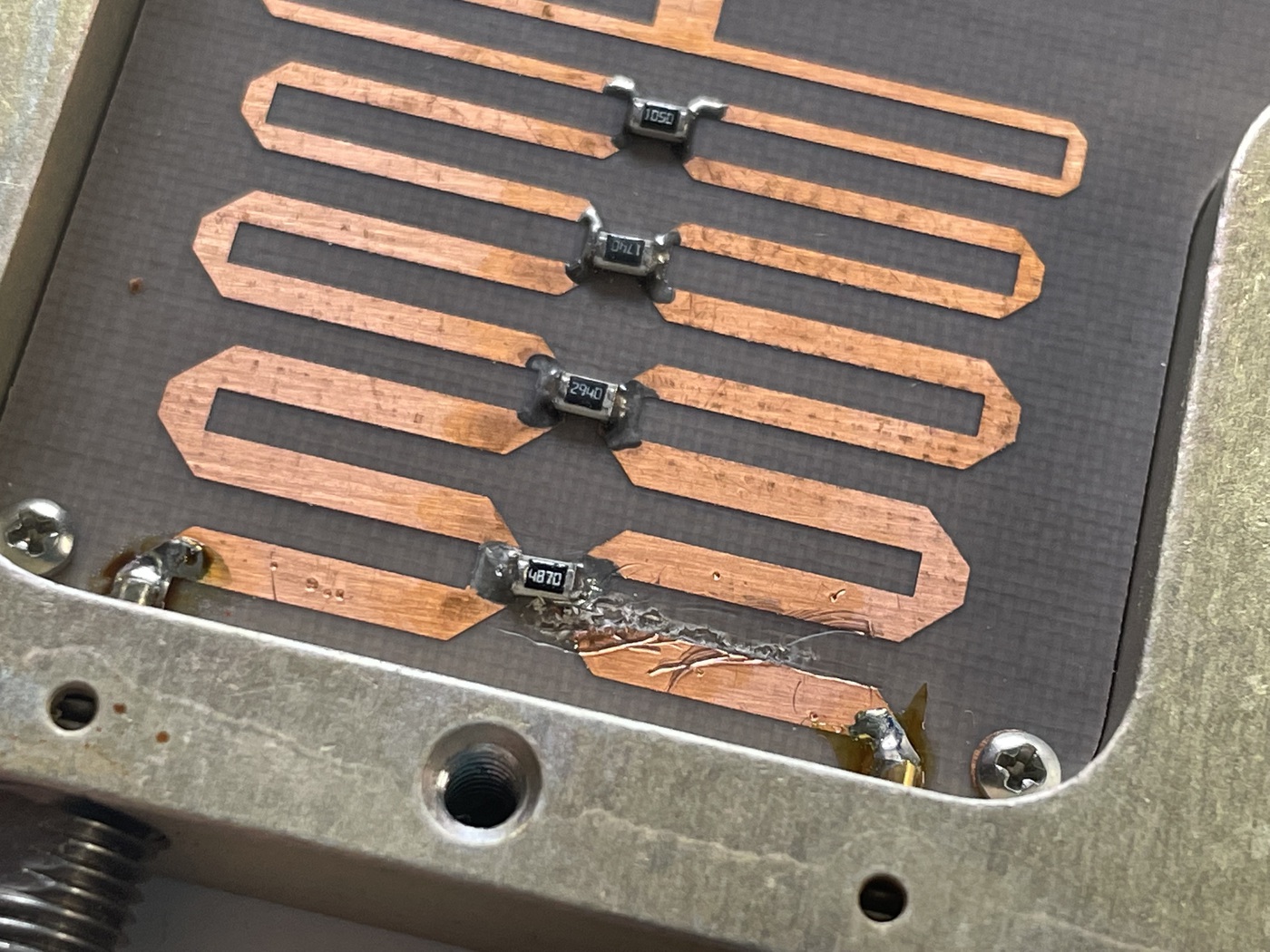
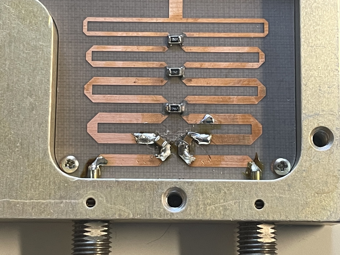
On the other side, the procedure was slightly different. I removed the bottom-most resistor in the chain, then cut out the copper between the traces and the pads that ran to each connector. Again, verify that these traces are completely removed.
Next, I soldered in two more capacitors across each of the breaks.
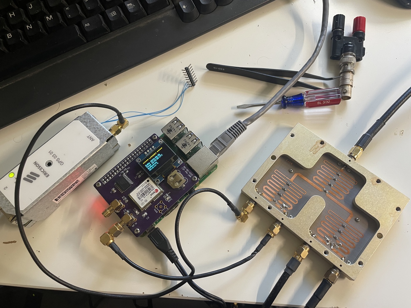
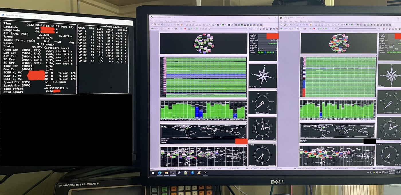
At this point, test the rest of the connectors and verify their operation. I had four receivers going on this splitter and each reporting many SVs with an SNR of over 40.
Finally, no project is complete without a slightly off-center label.
This was a fun and easy project that cost me less than $10 all in. Even if I had to buy a splitter at $30 it would have been well worth it. There are a lot of ways you could implement something like this yourself, as there are many different designs of RF splitters out there, not to mention different blocking capacitor values to try, as well as adding bleed resistors to trick the LNA-power monitors into thinking they are doing something.
I hope you found this post beneficial or at least interesting, and I'd love to hear from you either way!